Perfect Info About Can You Connect Ammeter And Voltmeter In A Circuit

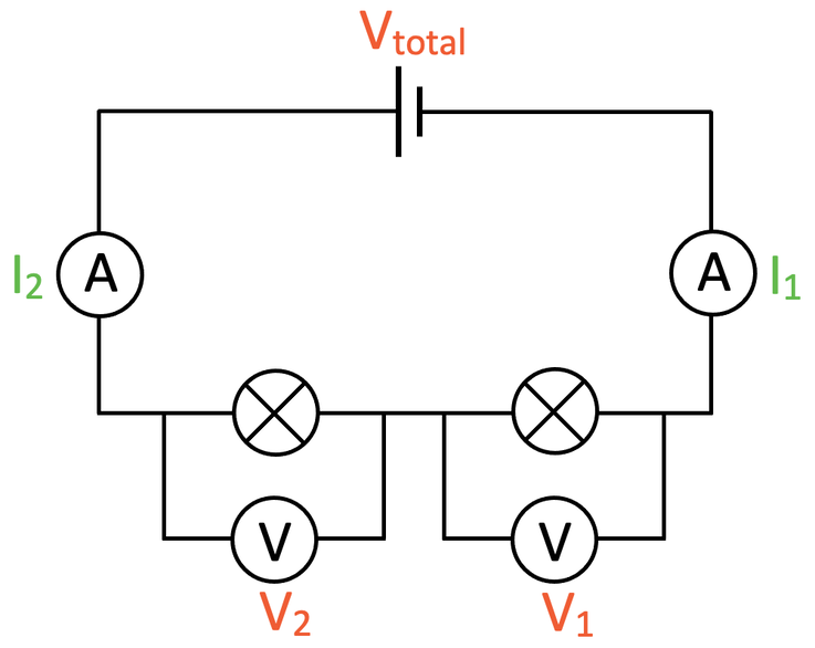
Ammeter And Voltmeter Connection Diagram At Jaclyn Glenn Blog
Understanding Ammeters and Voltmeters
1. What do these things even do?
Ever wondered how electricians know exactly how much juice is flowing through your wires, or the precise voltage powering your fridge? The answer lies in two handy tools: the ammeter and the voltmeter. Think of them as the doctor's stethoscope and blood pressure cuff for your electrical circuits. One tells you about the current (the flow of electrons, like water through a pipe), and the other tells you about the electrical potential difference (the "pressure" pushing those electrons, like water pressure). Pretty important stuff, right?
Now, connecting these devices isn't rocket science, but it's important to get it right. Messing with electricity can be dangerous if you're not careful! But don't worry; we're here to shed some light on the subject, making sure you understand the hows and whys of using these essential instruments. Forget the complicated jargon, we're going to explore this in a way that's easy to understand, even if you're just starting out.
So, are they interchangeable? Can you just plug them in any old way? The short answer is a resounding NO. There's a specific way to "connect ammeter and voltmeter in a circuit," and understanding that difference is key to getting accurate measurements and, more importantly, staying safe. Trust me, knowing the difference between series and parallel connections could save you from a nasty surprise!
Think of it like this: an ammeter is like a toll booth on a highway, measuring the flow of traffic. A voltmeter, on the other hand, is like measuring the height difference between two points on that highway. They're measuring completely different things, and therefore, need to be connected in completely different ways. Let's dive deeper into the specifics of how to connect each one.

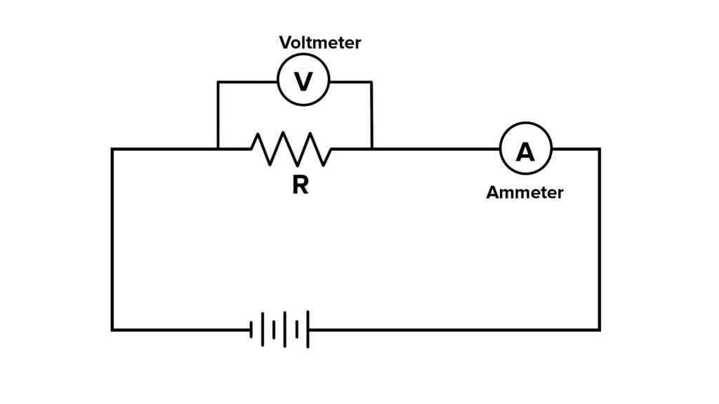
Simple Circuit Diagram With Ammeter And Voltmeter
Ammeter Connection
2. The Series Connection Explained
When you want to measure the current flowing through a circuit, you need to use an ammeter in what's called a "series" connection. Imagine a river with a water wheel in the middle. The water wheel is like your device, and the amount of water flowing through it is the current you're trying to measure. To measure that flow, you'd need to insert your measuring device (the ammeter) directly into the river, so all the water flows through it. That's a series connection in a nutshell.
This means you actually have to break the circuit at the point where you want to measure the current. Sounds a bit drastic, I know! You disconnect the wire, connect one end of the ammeter to one side of the break, and the other end of the ammeter to the other side. Essentially, the ammeter becomes part of the circuit itself. It's crucial that the ammeter has a very low internal resistance. Why? Because if it had high resistance, it would impede the flow of current, altering the reading and potentially damaging the ammeter itself. Remember, it's like adding a tiny pebble to the river; it shouldn't significantly change the flow.
Why cant you just connect the ammeter across the circuit like a voltmeter? Because an ammeter is designed to have extremely low resistance. Connecting it across a voltage source (in parallel) would create a short circuit, allowing a huge amount of current to flow through the ammeter, very likely blowing a fuse or even damaging the instrument. It's like opening the floodgates — not a good idea!
Always double-check that your ammeter is set to the correct range before connecting it. Ammeters typically have multiple ranges to accommodate different current levels. Starting with the highest range and working your way down is a safe bet. It prevents you from overloading the ammeter with too much current. And, of course, make sure the power to the circuit is OFF before you start messing around! Safety first, always!

Draw A Circuit Diagram Using Symbols Of An Ammeter And Voltmeter
Voltmeter Connection
3. Understanding Parallel Connections
Now, let's talk about voltmeters. Unlike ammeters, which measure the current flowing through a component, voltmeters measure the voltage across a component. Voltage, as we said, is like the electrical pressure that drives the current. To measure this "pressure," you need to connect the voltmeter in "parallel" with the component. Think of it like measuring the height difference between two points; you need to connect your measuring device (the voltmeter) to both points simultaneously, without interrupting the flow between them.
A parallel connection means you connect the voltmeter alongside the component you want to measure, without breaking the circuit. You attach one lead of the voltmeter to one side of the component and the other lead to the other side. The voltmeter acts like a tiny, almost imperceptible bypass around the component, measuring the potential difference (voltage) without significantly affecting the circuit's operation. The key here is that the voltmeter has very high internal resistance. Why? Because you don't want the voltmeter to draw a significant amount of current away from the component you're measuring. It's like barely sipping from a glass of water; you don't want to empty the glass!
Trying to connect a voltmeter in series would be like trying to measure the water pressure in a pipe by sticking a pressure gauge inside the pipe, blocking the flow. It wouldn't work, and you might even damage the pipe (or the voltmeter!). Because voltmeters have high internal resistance, inserting them in series would drastically reduce the current flow in the circuit.
Just like with ammeters, it's important to select the correct range on your voltmeter before making a measurement. Start with the highest range and work your way down until you get a suitable reading. And, as always, exercise caution when working with electricity. Double-check your connections and make sure you understand the circuit before you start measuring. Safety is paramount!

Why the Difference Matters
4. It's Not Just Theory, It's Practicality
So, why all this fuss about series and parallel connections? Well, it boils down to two crucial factors: safety and accuracy. Incorrectly connecting an ammeter or voltmeter can lead to inaccurate readings, damaged equipment, or even electrical shocks. Nobody wants that!
Connecting an ammeter in parallel, as we discussed, creates a short circuit. The ammeter's low internal resistance provides a very easy path for current to flow, bypassing the rest of the circuit. This can lead to a dangerously high current flow, potentially blowing fuses, damaging the ammeter, or even causing a fire. Think of it as creating a super-fast, unblocked lane on the highway; all the traffic will rush there, causing chaos!
Conversely, connecting a voltmeter in series introduces a high resistance into the circuit. This drastically reduces the current flow, potentially preventing the circuit from operating correctly. While this is less likely to cause immediate damage, it will certainly give you inaccurate readings and prevent you from understanding what's really going on in the circuit. It's like adding a huge speed bump to the highway; everything slows to a crawl.
By understanding the fundamental differences between series and parallel connections and by carefully following the correct procedures, you can safely and accurately measure current and voltage in your circuits. This knowledge is essential for anyone working with electronics, from hobbyists to professional electricians. Always remember: safety first, and accurate measurements second!

Practical Tips and Precautions
5. Keeping it Safe and Smart
Okay, so you understand the theory. Now, let's talk about some practical tips and precautions to keep you safe and your measurements accurate.
Always disconnect the power before connecting or disconnecting an ammeter or voltmeter. This is rule number one for a reason! Working on a live circuit is just asking for trouble. Even if you think you know what you're doing, accidents can happen. Turn off the power, double-check it's off, and then proceed. It's like making sure the car is in park before you start working on the engine.
Use the correct range on your meter. As we've mentioned before, starting with the highest range and working your way down is always a good idea. This prevents you from overloading the meter and potentially damaging it. Most digital multimeters (DMMs) have an auto-ranging feature that simplifies this process, but it's still good practice to understand the ranges involved.
Pay attention to the polarity of the leads. Ammeters and voltmeters are often polarity-sensitive, meaning they need to be connected with the correct positive and negative terminals. Reversing the polarity can give you a negative reading or, in some cases, damage the meter. Most meters have markings to indicate the positive and negative terminals, so pay close attention!
Finally, if you're ever unsure about something, don't hesitate to ask for help from a qualified electrician or electronics technician. Electricity is not something to be taken lightly, and it's always better to be safe than sorry. Remember, there's no shame in admitting you don't know something. It's a sign of intelligence, not ignorance.
