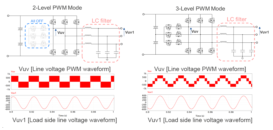
Heartwarming Info About What Is The Maximum Frequency Of PWM
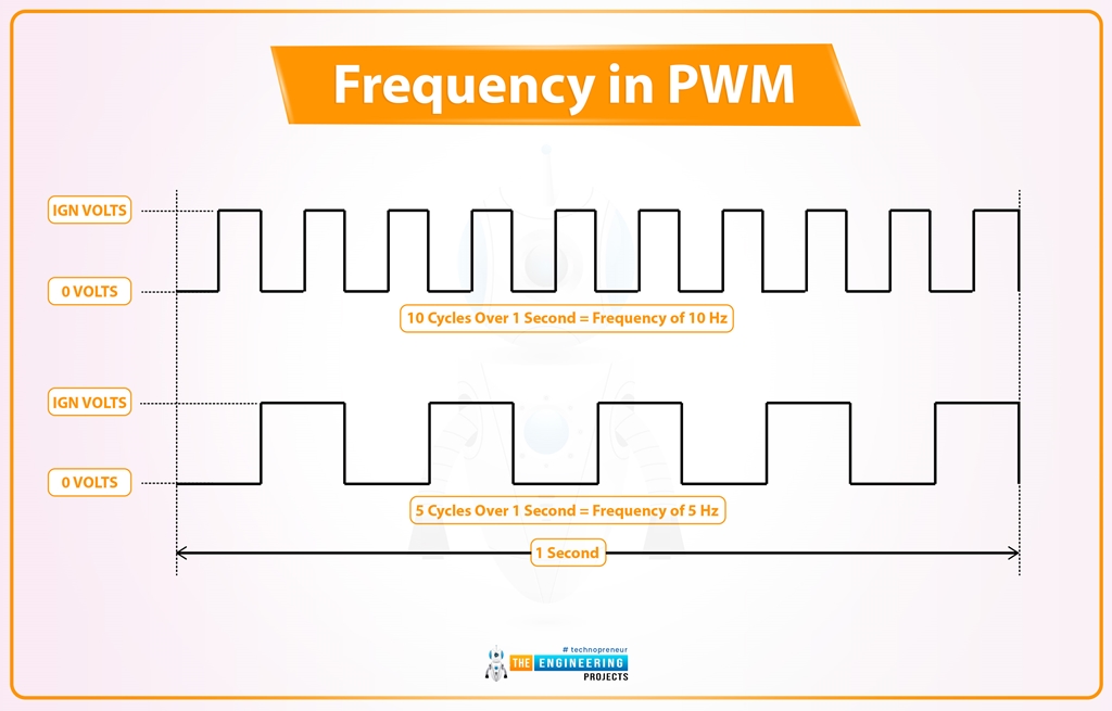
ESP32 PWM(Pulse Width Modulation) In Arduino IDE The Engineering Projects
Demystifying PWM Frequency
1. Understanding the Pulse Width Modulation Basics
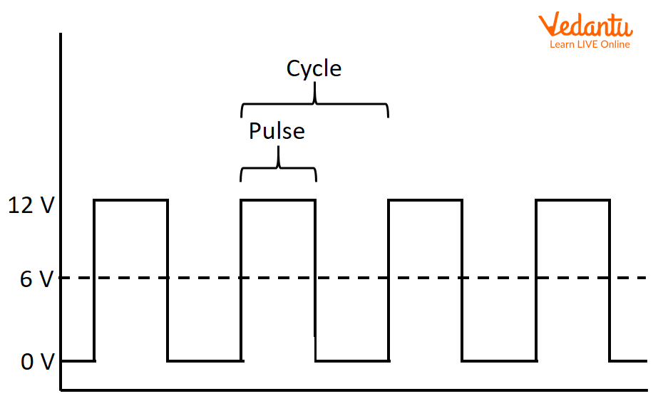
Ever wondered how devices like dimmer switches, motor speed controllers, and even your computer's cooling fan manage to fine-tune their performance? The secret often lies in a technique called Pulse Width Modulation, or PWM for short. Essentially, PWM is a clever way of controlling the amount of power delivered to a device by rapidly switching the power on and off. Think of it like flickering a light switch really, really fast. The longer the "on" time compared to the "off" time, the more power gets through.
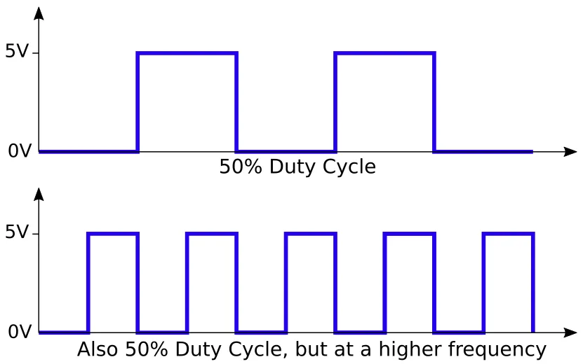
Now, the frequency of this switching action — that is, how many times per second the power cycles on and off — is what we're really interested in. This frequency is measured in Hertz (Hz), which simply means "cycles per second." A higher frequency means the power is switching on and off more rapidly, while a lower frequency means it's switching more slowly. But what's the maximum frequency PWM can handle? Well, that's where things get interesting, and a bit more complex.
Think of a juggler. If they are juggling oranges, they can keep a high rhythm going. If you swapped them for bowling balls, their top speed drops considerably! The same applies to the components that generate your PWM signal. Switching between on and off takes time, and the components have limits to how fast they can keep up.
So, while there isnt one single, universally agreed-upon maximum PWM frequency, we can delve into the factors that influence it and get a good sense of what to expect. It's a bit like asking "how fast can a car go?" It depends on the car, the driver, and the road conditions. Similarly, the maximum PWM frequency depends on the hardware, the application, and the desired performance characteristics.
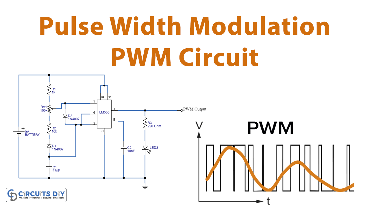
Pwm Pulse Width Modulation Simple Circuits Diagram Si Vrogue.co
The Factors Limiting Maximum PWM Frequency
2. Component Limitations and Switching Speeds
One of the biggest constraints on the maximum PWM frequency is the switching speed of the electronic components used to generate the PWM signal. Transistors, for instance, need a certain amount of time to switch from the "off" state to the "on" state, and vice versa. This switching time isn't instantaneous; it takes a tiny fraction of a second. But at very high frequencies, this switching time becomes a significant portion of the entire PWM cycle, which can lead to inaccuracies and inefficiencies.
Imagine trying to flip a light switch on and off 1 million times per second if the switch itself takes a thousandth of a second to actually change state. You just wouldn't be able to keep up, and the resulting light output would be pretty erratic. This is especially true for high voltage or high current applications. The more energy you're switching, the slower the process becomes.
Moreover, every switch generates heat. Heat is the bane of electronics, reducing the lifetime and efficiency of your components. Pushing your system to operate at the very edge of its rated speed could result in overheating, component failures, and generally unhappy electronics. So, designing within safe operating margins is always a good idea.
Therefore, the characteristics of the specific transistor or other switching device being used will heavily influence the practical upper limit of the PWM frequency. Faster components generally allow for higher frequencies, but they also tend to be more expensive and may have other trade-offs.
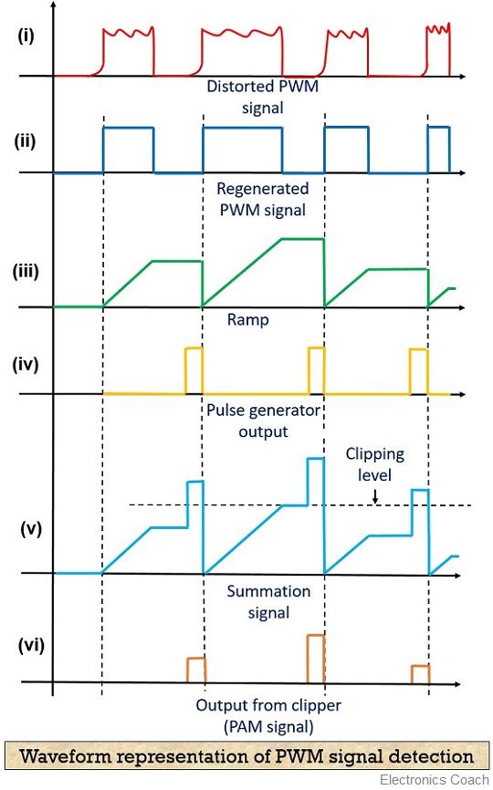
What Is Pulse Width Modulation (PWM)? Definition, Basics,, 51 OFF
Impact on Different Applications
3. Balancing Speed and Precision
The ideal PWM frequency often depends on the application. In some cases, a high frequency is crucial for smooth and precise control. For instance, in audio amplifiers, a high PWM frequency can help to minimize distortion and noise, resulting in a cleaner sound. The higher the PWM frequency, the less noticeable the switching artifacts become.
On the other hand, in applications where efficiency is paramount, a lower PWM frequency might be preferable. Lower frequencies generally lead to lower switching losses, which means less energy is wasted as heat. This is particularly important in battery-powered devices, where every bit of energy conservation counts. Consider controlling a large motor. The sheer size and inertia of the motor will smooth out variations caused by a slower PWM rate, and you dont need the same precision as an audio amplifier.
There's also the issue of electromagnetic interference (EMI). Higher PWM frequencies can sometimes generate more EMI, which can interfere with other electronic devices. If EMI is a concern, it might be necessary to use shielding or filtering techniques, or to simply reduce the PWM frequency. In sensitive environments like medical equipment, this is something that you would seriously consider.
Therefore, choosing the right PWM frequency involves striking a balance between speed, precision, efficiency, and EMI. There's no one-size-fits-all answer, and the optimal frequency will depend on the specific requirements of the application.
PWM (Pulse Width Modulation) Learn Important Terms And Concepts
Practical Considerations and Trade-Offs
4. Filtering and Audible Noise
When selecting a PWM frequency, engineers must consider the potential for audible noise. If the PWM frequency falls within the human hearing range (roughly 20 Hz to 20 kHz), the switching action can produce an annoying buzzing or whining sound. This is especially common in devices that drive speakers or motors. Its an incredibly irritating sound once you hear it; like a mosquito in your ear. Choosing a PWM frequency outside of this range is generally a good idea to avoid this issue. Often, choosing a rate above 20KHz is easiest as you are relying on the component itself to move to fast to physically create the tone.
Another important consideration is the need for filtering. A PWM signal is essentially a square wave, which contains a lot of high-frequency harmonics. These harmonics can sometimes cause unwanted interference or distortion. To mitigate this, engineers often use low-pass filters to smooth out the PWM signal and remove the unwanted harmonics. The higher the PWM frequency, the easier it is to filter out these harmonics. Imagine trying to smooth out a bumpy road. The more often the bumps, the easier it is to smooth the overall path. Similar principles apply here.
Additionally, the complexity and cost of the control circuitry can also play a role. Generating a very high PWM frequency requires more sophisticated and expensive hardware. In some cases, it might be more cost-effective to use a lower PWM frequency and compensate with more advanced filtering techniques. Sometimes, you have to pick your battles and go with the option that provides the best overall value. After all, the goal is to achieve the desired performance at the lowest possible cost. This can include both component cost and power consumption.
Ultimately, designing an effective PWM system involves carefully weighing all of these factors and making informed trade-offs. It's a balancing act that requires a good understanding of both the underlying theory and the practical limitations of the hardware.
So, What's the Real Maximum?
5. There is no simple answer
Okay, so we've discussed all the influencing factors, but you are still probably wondering, What number do I need to know? Sadly, there's no single "maximum" PWM frequency that applies to all situations. However, in many common microcontroller-based applications, PWM frequencies typically range from a few hundred Hertz to several hundred kilohertz.
For example, audio amplifiers might use PWM frequencies in the tens or hundreds of kilohertz to ensure high fidelity. Motor controllers, on the other hand, might use frequencies in the few kilohertz range to optimize efficiency. LED dimming applications often use frequencies in the hundreds of Hertz to avoid flicker. Ultimately, the selection boils down to the specific requirements of the application, the capabilities of the hardware, and the desired performance characteristics.
The best approach is often to experiment and test different PWM frequencies to find the optimal setting for a particular application. Start with a relatively low frequency and gradually increase it until you start to see diminishing returns or encounter problems such as excessive noise or distortion. Keep detailed records of your testing and be sure to document your findings. This process of trial and error can be time-consuming, but it's often the most effective way to determine the maximum practical PWM frequency for a given situation.
And, of course, always consult the datasheets for your specific electronic components. These datasheets will provide valuable information about the maximum switching speeds and other performance characteristics of your components, which can help you to avoid pushing them beyond their limits. Remember, electronics are like people — they perform best when they're not being pushed to the breaking point.
Arduino In C++
