Inspirating Tips About What Is The Formula For Continuity Resistance

What Is Formula Of Present Continuous Tense Free Printable
Understanding Continuity Resistance
1. What Exactly Is Continuity Resistance?
Okay, let's break this down. You've probably heard the term "continuity resistance" thrown around, especially if you're dealing with electrical circuits. But what does it actually mean? Simply put, continuity resistance is a measure of how easily electricity can flow through a circuit or a component. When we are talking about the the flow of electricity through a circuit or components, we are also talking about how complete and unbroken the current path is.
Think of it like water flowing through a pipe. A wide, clean pipe allows water to flow freely, right? That's low resistance, or good continuity. A narrow, clogged pipe restricts the water flow — that's high resistance, or poor continuity. In electrical terms, low resistance means the circuit is complete and electricity can flow without much impediment. High resistance, on the other hand, suggests a break or a significant obstruction in the circuit.
So, why is understanding continuity resistance important? Well, it's crucial for troubleshooting electrical problems. If a circuit isn't working, checking continuity resistance can quickly tell you if there's a broken wire, a loose connection, or a faulty component. Its like a quick health check for your electrical system!
And the key term here is resistance, which is a noun. This understanding is essential for effectively grasping the formula and its applications. It is quite essential to understand, the amount of resistance is a physical quantity that can be measured.

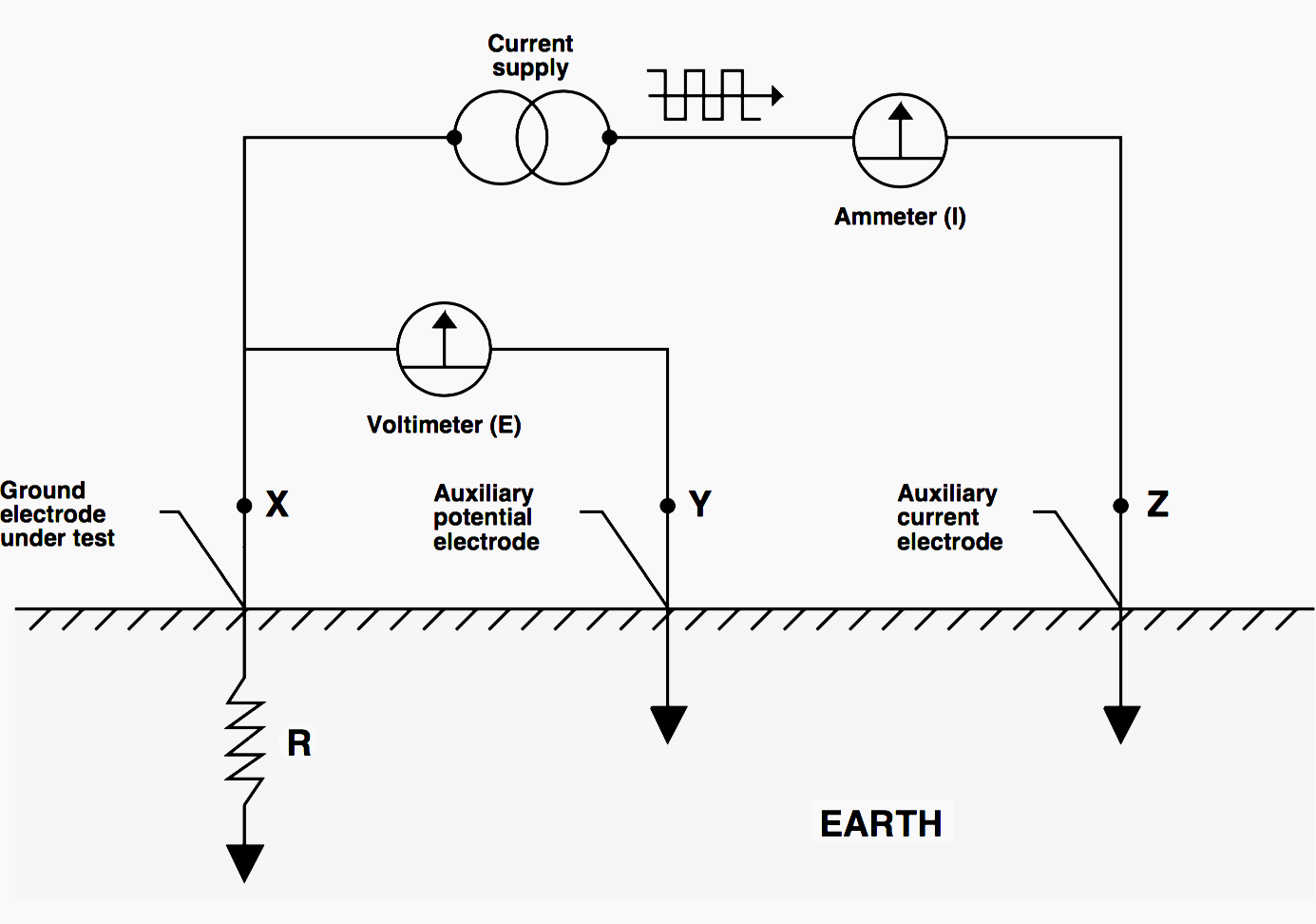
Grounding Resistance Test Procedure Printable Templates Protal
The Continuity Resistance Formula
2. What's the Magic Formula?
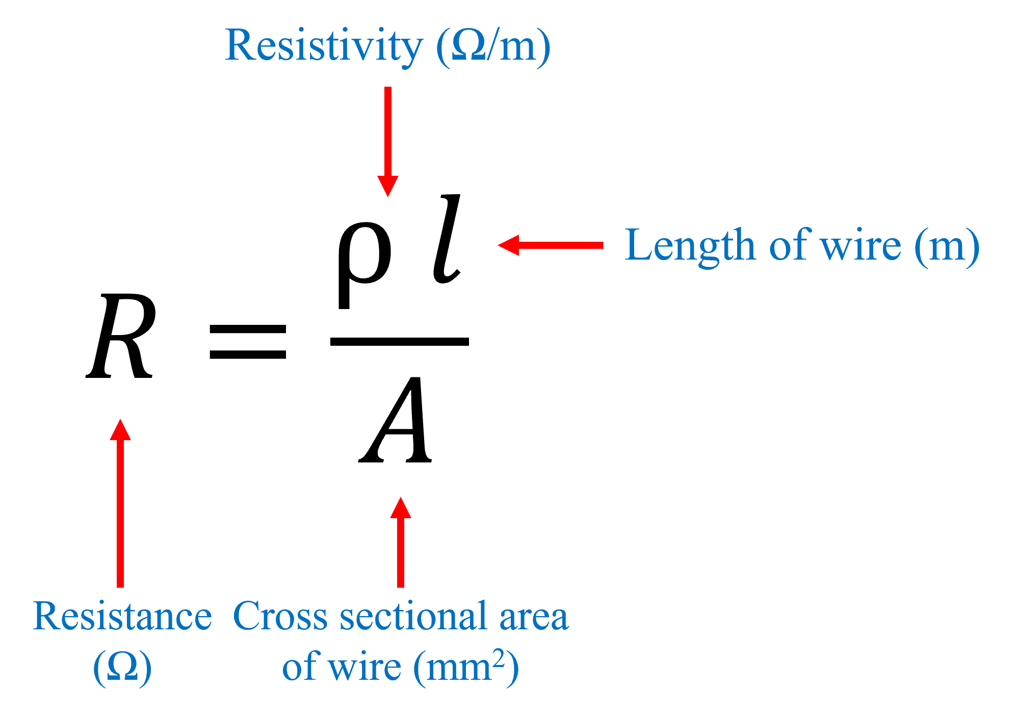
Alright, let's get down to brass tacks. The formula for determining resistance relies on Ohm's Law, a cornerstone of electrical theory. Now, Ohm's Law in its most basic form is: V = IR. But let's not get scared by letters. V stands for Voltage (measured in Volts), I stands for Current (measured in Amperes), and R stands for Resistance (measured in Ohms). Think of it as Voltage pushing the current through the resistor.
To find the resistance, we simply rearrange the formula to solve for R: R = V / I. This tells us that resistance is equal to voltage divided by current. It's a straightforward calculation, but its implications are powerful. By measuring the voltage across a component or circuit and the current flowing through it, we can accurately determine its resistance.
Now, when we specifically talk about "continuity resistance", we often imply we are checking if a path exists for current to flow. In that case, you'd ideally want the resistance to be close to zero. A high resistance reading would indicate a break in the circuit, meaning it's not continuous. In many cases, a multimeter is used to perform this, and has a continuity setting.
Its important to remember that this formula applies when you can accurately measure both voltage and current. In many continuity checks, particularly when using a multimeter's continuity setting, the meter itself provides a small voltage and measures the resulting current to determine the resistance. The meter then typically displays a reading (often near zero for good continuity) or an audible beep to indicate a continuous path.

Continuity Equation Definition, Equation, Formula And Examples PDF
Tools of the Trade
3. Equipping Yourself for the Task
So, you know the formula, but what do you need to actually measure continuity resistance? The most common tool for this job is a multimeter, sometimes called a voltmeter, or a multi-tester. These versatile devices can measure voltage, current, and – you guessed it – resistance. Many multimeters even have a dedicated "continuity" setting, which makes checking for breaks in a circuit a breeze.
When using a multimeter to check continuity, you'll typically connect the probes to the two points you want to test. If the meter beeps or shows a very low resistance reading (close to zero Ohms), it means there's a continuous path between those points. If the meter doesn't beep or shows a very high resistance (often indicated by "OL" for Overload), it means the circuit is broken and there's no continuity.
Beyond a multimeter, sometimes a dedicated continuity tester is used, especially in applications where quick and easy checks are needed. These testers are simpler than multimeters and are specifically designed to detect continuity. They typically have a light or a buzzer that activates when a continuous path is detected.
Safety first! Before checking continuity, always make sure the circuit you're testing is de-energized. Disconnect the power source to prevent electrical shock or damage to your equipment. And remember to double-check your connections to ensure accurate readings. Nobody wants to chase a ghost because of a loose probe!

Real-World Applications
4. Putting the Knowledge to Work
Now that we've covered the theory and the tools, let's look at some practical applications. Where does understanding continuity resistance actually come in handy? The applications are vast, ranging from simple household repairs to complex industrial maintenance.
One common application is troubleshooting electrical wiring in your home. If a light switch isn't working, checking the continuity of the wiring can quickly reveal whether there's a break in the circuit. Similarly, if an appliance isn't powering on, checking the continuity of the power cord can help you identify a faulty cord or plug. Diagnosing car issues often requires you to check the continuity of certain circuits.
In industrial settings, continuity testing is essential for maintaining machinery and equipment. Checking the continuity of motor windings, control circuits, and safety interlocks can help prevent costly downtime and ensure the safe operation of equipment. Electricians and maintenance technicians rely on continuity testing to quickly identify and resolve electrical problems.
Continuity testing is also crucial in electronics manufacturing. Checking the continuity of printed circuit boards (PCBs) ensures that the connections between components are intact and that there are no shorts or open circuits. This helps prevent defects and ensures the reliability of electronic devices.

Troubleshooting Tips & Common Pitfalls
5. Avoiding the Resistance Rabbit Hole
Even with a solid understanding of continuity resistance and the right tools, troubleshooting electrical problems can sometimes be tricky. Here are a few tips and common pitfalls to avoid:
First, always double-check your connections. A loose or corroded connection can give you a false reading, leading you down the wrong path. Clean the contacts with a wire brush or contact cleaner to ensure a good connection. And make sure your multimeter probes are making solid contact with the circuit you're testing.
Second, be aware of parallel paths. Sometimes, there may be multiple paths for current to flow between two points in a circuit. This can give you a false continuity reading even if there's a break in one of the paths. To isolate the circuit you're testing, disconnect components or wires to eliminate parallel paths.
Third, don't assume that a low resistance reading always means good continuity. In some cases, a low resistance reading could indicate a short circuit, where current is flowing through an unintended path. Always investigate further to determine the root cause of the problem.
Finally, trust your gut. If something doesn't seem right, don't be afraid to ask for help or consult a qualified electrician. Electrical troubleshooting can be dangerous, and it's always better to err on the side of caution.